How to Run FEA

Finite Element Analysis (FEA). How does it happen? What is the general process for how to produce a quality FEA analysis, from start to finish? As a client, what do you get when you pay for FEA? No one should become an expert just to purchase FEA services, but we all do benefit from a basic knowledge of the FEA process.
It’s good to know the general FEA process. This allows you to negotiate with reasonable expectations and understand the limitations of your service provider. Figure 2‑1 shows the general work sequence that an FEA analyst goes through.

The geometry is where it all starts. Eventually, the engineer will need to build an accurate 3D model for the FEA analysis. They will need any geometry that defines the ship section. If you wish to install new equipment, the engineer needs the details about that equipment, and the structural details of the ship at the installation location. The engineer will likely need to build a new 3D model specific to the FEA, even if you supply a 3D model as a starting point. This is for three main reasons:
Next the engineer constrains the model, specifying sections where the structure cannot move. We use these constraints to define the conditions at the edges of the FEA model. After constraints, the loads specify all the actions on the model. This may be any of a number of things:
Remember that in most cases, you will need more than one load case. Normally the engineer needs to check several different load combinations. Part of their work is to define all those load cases, check if any more are required.
The mesh is what drives the magic of FEA. (Figure 2‑2) Take a big complicated ship and break it into many tiny little pieces. The engineer tries to minimize the cell count in the mesh by focusing small cells only where required. More cells mean more computing time and higher budgets. By current standards (2018):
You can expect the engineer to generate multiple meshes. Getting the right mesh is partly trial and error. And multiple meshes are required for the mesh convergence study.
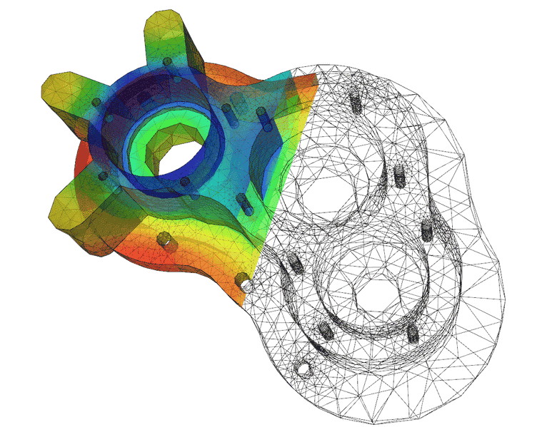
The haunting question of any mesh generation: what is the right size for the mesh. We all have guidelines, but no one can predict the exact size of cell required for each FEA analysis. True certainty requires the engineer to run a mesh convergence study. Also called a mesh independence study, this should be included as part of the standard FEA analysis. The mesh convergence study is a major part of the quality control for the FEA.
As part of the quality control, the engineer develops some simplified hand calculations and compares them to the FEA predictions. These hand calculations provide a sensibility check. The FEA should definitely be more accurate, but any outputs are still within the same range as the hand calculations. These calculations rarely make it into the final report. They just form part of the quality control that allows you to confidently trust the FEA.
The model works! Now to create the actual requested outputs. This takes a surprising amount of time. Normally the FEA results go into a report, and the report requires a shocking number of 2D pictures to show every detail of a 3D model. Typically, the engineer provides several overview pictures and then focuses on the few details of interest in the model.
Some software allows the engineer to provide results as a 3D file that you can view with a free viewer. Ask if you can get this option. This may be a good compromise that allows you to see all the details and saves the engineer from spending hours generating photos.

Finally, the engineer should summarize all their analysis work and results in a report. An FEA report has a few additional requirements beyond standard engineering reports. The FEA report needs to demonstrate reason for confidence in the model. Expect the following elements from the report:
One major contention: clients sometimes want a copy of the FEA model. This is the equivalent of asking a doctor if you can perform your own X-rays. Engineers tend to resist because the FEA model also contains all their proprietary settings. Plus you need the same FEA software to even open the file. Most engineers prefer to hold back their model, but they usually provide it to 3rd parties for review. For example: send the model to ABS for review by class society. These requests go smoother if you identify a specific reason for the engineer to provide a copy of the model.
Finite Element Analysis (FEA). The process. The science. You don’t need expertise to benefit from FEA services. The engineer delivers all that background knowledge wrapped into a tidy report. But we all benefit from a basic understanding of the process and applications. Begin with reasonable expectations for an FEA analysis and monitor with an understanding of the overall process.
| [1] | U. A1, “Elmer Pump Heat Equation,” Wikimedia Commons, 2 Jun 2010. . Available: https://commons.wikimedia.org/wiki/File:Elmer-pump-heatequation.png. . |
| [2] | Dcoetzee, “Block Matrix Multiplication,” Wikimedia Commons, 4 Sep 2012. . Available: https://commons.wikimedia.org/wiki/File:Block_matrix_multiplication.svg. . |
 https://dmsonline.us/wp-content/uploads/2023/12/HabbakukCover-Small-1.jpg
489
500
Nate Riggins
/wp-content/uploads/2025/06/DMS-logo.svg
Nate Riggins2024-09-24 09:18:002026-02-23 09:10:05Project Habbakuk: A Ship from Ice!
https://dmsonline.us/wp-content/uploads/2023/12/HabbakukCover-Small-1.jpg
489
500
Nate Riggins
/wp-content/uploads/2025/06/DMS-logo.svg
Nate Riggins2024-09-24 09:18:002026-02-23 09:10:05Project Habbakuk: A Ship from Ice!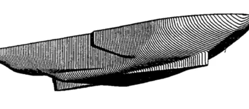 https://dmsonline.us/wp-content/uploads/2023/12/Icebreaker_SpoonBow.webp
217
598
Nate Riggins
/wp-content/uploads/2025/06/DMS-logo.svg
Nate Riggins2024-07-16 09:00:002026-02-23 09:10:05Strong as Ice: Icebreaker Structure
https://dmsonline.us/wp-content/uploads/2023/12/Icebreaker_SpoonBow.webp
217
598
Nate Riggins
/wp-content/uploads/2025/06/DMS-logo.svg
Nate Riggins2024-07-16 09:00:002026-02-23 09:10:05Strong as Ice: Icebreaker Structure https://dmsonline.us/wp-content/uploads/2023/12/USCGC_Healy_WAGB-20_north_of_Alaska-scaled-1.jpg
633
1200
Nate Riggins
/wp-content/uploads/2025/06/DMS-logo.svg
Nate Riggins2024-05-14 09:00:002026-02-23 09:10:06Surviving the Arctic: Polar Class Icebreakers
https://dmsonline.us/wp-content/uploads/2023/12/USCGC_Healy_WAGB-20_north_of_Alaska-scaled-1.jpg
633
1200
Nate Riggins
/wp-content/uploads/2025/06/DMS-logo.svg
Nate Riggins2024-05-14 09:00:002026-02-23 09:10:06Surviving the Arctic: Polar Class Icebreakers https://dmsonline.us/wp-content/uploads/2023/12/MackinawIce1-scaled-1.jpg
883
1200
Nate Riggins
/wp-content/uploads/2025/06/DMS-logo.svg
Nate Riggins2024-03-19 09:00:002026-02-23 09:10:06Ramming the Ice: Icebreaker Propulsion
https://dmsonline.us/wp-content/uploads/2023/12/MackinawIce1-scaled-1.jpg
883
1200
Nate Riggins
/wp-content/uploads/2025/06/DMS-logo.svg
Nate Riggins2024-03-19 09:00:002026-02-23 09:10:06Ramming the Ice: Icebreaker Propulsion https://dmsonline.us/wp-content/uploads/2023/12/MackinawIce2-scaled-1.jpg
1200
985
Nate Riggins
/wp-content/uploads/2025/06/DMS-logo.svg
Nate Riggins2024-01-16 09:00:002026-02-23 09:10:06Breaking the Ice: Icebreakers
https://dmsonline.us/wp-content/uploads/2023/12/MackinawIce2-scaled-1.jpg
1200
985
Nate Riggins
/wp-content/uploads/2025/06/DMS-logo.svg
Nate Riggins2024-01-16 09:00:002026-02-23 09:10:06Breaking the Ice: Icebreakers https://dmsonline.us/wp-content/uploads/2022/06/MVAltairGeneralArrangementPlan_SmallResolution.webp
299
640
Nate Riggins
/wp-content/uploads/2025/06/DMS-logo.svg
Nate Riggins2022-09-12 06:00:002025-09-30 07:31:20How to Design a Ship
https://dmsonline.us/wp-content/uploads/2022/06/MVAltairGeneralArrangementPlan_SmallResolution.webp
299
640
Nate Riggins
/wp-content/uploads/2025/06/DMS-logo.svg
Nate Riggins2022-09-12 06:00:002025-09-30 07:31:20How to Design a Ship https://dmsonline.us/wp-content/uploads/2020/12/Composite_3d.png
600
800
Nate Riggins
/wp-content/uploads/2025/06/DMS-logo.svg
Nate Riggins2021-01-04 07:00:002026-02-23 09:10:07Composite Materials
https://dmsonline.us/wp-content/uploads/2020/12/Composite_3d.png
600
800
Nate Riggins
/wp-content/uploads/2025/06/DMS-logo.svg
Nate Riggins2021-01-04 07:00:002026-02-23 09:10:07Composite Materials https://dmsonline.us/wp-content/uploads/2018/11/M18016_FeatureImage.jpg
720
1280
Nate Riggins
/wp-content/uploads/2025/06/DMS-logo.svg
Nate Riggins2019-03-18 08:30:532026-02-23 09:10:16Six Ways to Break the Ship
https://dmsonline.us/wp-content/uploads/2018/11/M18016_FeatureImage.jpg
720
1280
Nate Riggins
/wp-content/uploads/2025/06/DMS-logo.svg
Nate Riggins2019-03-18 08:30:532026-02-23 09:10:16Six Ways to Break the Ship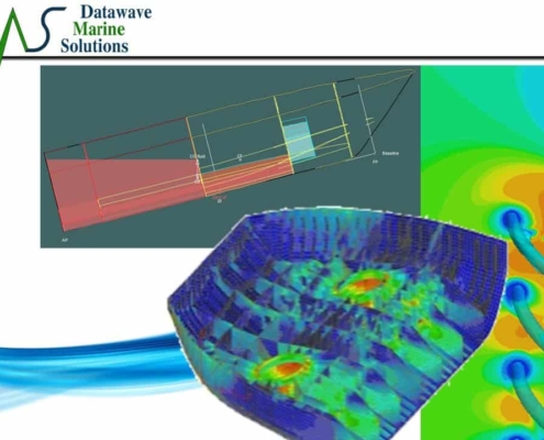 https://dmsonline.us/wp-content/uploads/2018/11/M18013_FeatureImage.jpg
720
1280
Nate Riggins
/wp-content/uploads/2025/06/DMS-logo.svg
Nate Riggins2019-02-18 08:30:162026-02-23 09:10:17Improve Engineering Value
https://dmsonline.us/wp-content/uploads/2018/11/M18013_FeatureImage.jpg
720
1280
Nate Riggins
/wp-content/uploads/2025/06/DMS-logo.svg
Nate Riggins2019-02-18 08:30:162026-02-23 09:10:17Improve Engineering Value