Six Keys to Better Marine FEA

No matter how much work you do in finite element analysis (FEA), there is always room for improvement. Masters of FEA trade-craft hoard many little tricks and nuggets of wisdom to deliver better FEA. These tricks yield better ways to detect human errors and ensure model reliability. Or methods to deliver faster results. Today we share six nuggets of wisdom for better FEA.
Do not model everything as solid elements. Most of the ship structure gets modeled with FEA plate elements. These are 2D surface elements that require far less computational effort than a 3D solid. Unlike simple 2D plane stress elements, plate elements also recognize rotational degrees of freedom for the nodes. This allows you to model plate bending, a key element of the ship structure.
For mesh sizing of your plate elements, element sizes should not become smaller than the plate thickness of the section you are meshing. [1] If you need smaller elements to capture the changing stress gradients, switch to a 3D solid element in those regions. When stresses change so rapidly, the plane strain assumptions of plate elements no longer apply. That is what drives the need for 3D solid elements in regions of high mesh density. But for the remaining 99% of the structure, save the computational workload and use plate elements.
Many FEA guides publish recommendations for mesh sizing. [2] Do not trust these as the ultimate authority on mesh sizes; they only serve as the starting point. As the engineer, you alone are entrusted to guarantee the accuracy of this model. Test your mesh settings. Perform mesh independence studies to confirm accuracy.
Conventional wisdom might lead you to model all your stiffeners as line elements (linear beams). Save yourself some time and just model everything as a plate element. Most FEA models are built from a starting geometry, which often includes the stiffeners. It requires minimal time to take that stiffener surface and specify a thickness for the whole thing. If you go the other route, you model each stiffener as a separate line element attached to the plate. Except now you must enter many properties to define each stiffener. Multiple opportunities for typos and mistakes. Save the time and the risk; use plate elements.
The convenience of plate elements also requires the wisdom to apply the correct mesh settings. Those mesh sizes now need to capture stress variation across the web of the stiffener. Most guides recommend a minimum of three elements across the stiffener web. [1] This allows the model to capture any nonlinear variation in the stress across the depth of the web.
Temptation beckons us to model welded joints as bonded connections. The software developers advertise this as a magic solution. Simply place the parts together and let the software automatically create connections. Don’t do it. Resist temptation.
Automatic bonded connections hurt you on three fronts. First, ship structures are too dense for the software to reliably detect the connections automatically. Every time I tried, the software created ridiculous connections that completely misrepresented the structure. Imagine testing a crane foundation by assuming the bottom of the crane pedestal magically links to the keel. The automatic connections often create those erroneous links.
The second reason to avoid bonded connections is the increase to computational time. For many analyses, these connecting links get rechecked and reformed at every timestep, accumulating mountains of un-needed computing time.
Finally, bonded connections remove your control over the quality of the model mesh at these critical joints. The FEA software randomly forms connections, simply searching for the closest nodes. That leads to ill-formed elements and unrealistic transfers of stress. Remember that stiffener connections are often the initiation sites for failure. You want high quality meshes at these critical welded joints.
Merged meshes answer the need for simple connections between parts. For a merged mesh, the software replaces the nodes from one part and substitutes in the nodes along the shared line. Two sets of nodes become one set, and both parts get regenerated as a single continuous mesh. This eliminates the added computing time and restores your control over mesh settings.
Ship structures begin FEA as a collection of unconnected parts. The engineer then connects all those parts into a single assembly . . . unless they miss a part. This happens regularly, since maritime FEA models may incorporates dozens to hundreds of parts. Save yourself the grief of rerunning a model. Employ this trick to quickly identify any runaway parts.
Analyze your model to identify the first five resonant frequencies. Don’t worry about the details of the frequencies or pretension. We want the mode shapes. Plot the mode shapes on a displacement plot, and those uncoupled parts light up as bright red patches of movement. Unconnected parts move freely, calling attention to their free movement. Now you know which parts you missed. This one trick easily prevents a whole day of lost work.
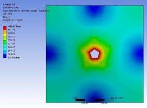
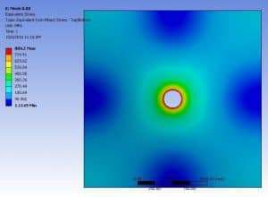
Stress singularities are a quirk of FEA. We see them more often in maritime structures, due to the heavy use of plate elements. When you see small points of peak stresses, be sure to check for stress singularities. Do not mistake them for stress concentrations. Mistaken points result in unnecessary plate thickness, extra weight, and extra costs to the client.
Once identified, there are several ways to handle a singularity. Simply ignore it if that spot is not critical. For more critical areas, you need to replace the geometry in that section with something that does not generate singularities. (Table 1)
| Geometry | Replacement |
| Weld joint (line) | 3D full thickness weld, with solid elements |
| Right angle hole | Filleted hole corners |
| Right angle plate bend | Radius plate bend |
These replacements are best employed as a sub-model of the major assembly. Place the small details in a small model, and copy over the stress patterns from the surrounding structure. This allows sharp focus for important points in the ship structure.
These little tips may be simple, but the best secrets often are. An experienced engineer doesn’t have some magic button to deliver great FEA. Experience demonstrates the wisdom learned as the engineer master dozens of small problems with each FEA model. As a result, every FEA model is better than the last one. That is the value of modelling tips: the wisdom of experience.
| [1] | American Bureau of Shipping, Guide for Safehull Dynamic Loading Approach for Vessels, Houston, TX: American Bureau of Shipping, February 2014. |
| [2] | American Bureau of Shipping, Guidance Notes on Safehull Finite Element Analysis of Hull Structures, Houston, TX: American Bureau of Shipping, February 2014. |
 https://dmsonline.us/wp-content/uploads/2022/06/Clickbait_2.66.3.jpg
1080
1920
Nate Riggins
/wp-content/uploads/2025/06/DMS-logo.svg
Nate Riggins2022-08-08 06:00:002025-07-23 09:49:36Lying with Numbers
https://dmsonline.us/wp-content/uploads/2022/06/Clickbait_2.66.3.jpg
1080
1920
Nate Riggins
/wp-content/uploads/2025/06/DMS-logo.svg
Nate Riggins2022-08-08 06:00:002025-07-23 09:49:36Lying with Numbers https://dmsonline.us/wp-content/uploads/2022/06/Clickbait_2.63.1.jpg
1080
1920
Nate Riggins
/wp-content/uploads/2025/06/DMS-logo.svg
Nate Riggins2022-07-11 06:00:002025-08-15 10:45:34The Value of Life
https://dmsonline.us/wp-content/uploads/2022/06/Clickbait_2.63.1.jpg
1080
1920
Nate Riggins
/wp-content/uploads/2025/06/DMS-logo.svg
Nate Riggins2022-07-11 06:00:002025-08-15 10:45:34The Value of Life https://dmsonline.us/wp-content/uploads/2021/04/Inspector.jpg
930
768
Nate Riggins
/wp-content/uploads/2025/06/DMS-logo.svg
Nate Riggins2021-04-05 07:00:002026-06-01 10:09:23Class Societies
https://dmsonline.us/wp-content/uploads/2021/04/Inspector.jpg
930
768
Nate Riggins
/wp-content/uploads/2025/06/DMS-logo.svg
Nate Riggins2021-04-05 07:00:002026-06-01 10:09:23Class Societies https://dmsonline.us/wp-content/uploads/2020/12/KitBoat.jpg
327
436
Nate Riggins
/wp-content/uploads/2025/06/DMS-logo.svg
Nate Riggins2021-02-01 07:00:002026-06-01 10:09:245 Steps to (NOT) Build a Boat
https://dmsonline.us/wp-content/uploads/2020/12/KitBoat.jpg
327
436
Nate Riggins
/wp-content/uploads/2025/06/DMS-logo.svg
Nate Riggins2021-02-01 07:00:002026-06-01 10:09:245 Steps to (NOT) Build a Boat https://dmsonline.us/wp-content/uploads/2020/12/Composite_3d.png
600
800
Nate Riggins
/wp-content/uploads/2025/06/DMS-logo.svg
Nate Riggins2021-01-04 07:00:002026-06-01 10:09:25Composite Materials
https://dmsonline.us/wp-content/uploads/2020/12/Composite_3d.png
600
800
Nate Riggins
/wp-content/uploads/2025/06/DMS-logo.svg
Nate Riggins2021-01-04 07:00:002026-06-01 10:09:25Composite Materials https://dmsonline.us/wp-content/uploads/2020/03/M20001_Clickbait_1.png
924
1643
Nate Riggins
/wp-content/uploads/2025/06/DMS-logo.svg
Nate Riggins2020-05-11 06:00:002026-06-01 10:09:29What is a Stability Test
https://dmsonline.us/wp-content/uploads/2020/03/M20001_Clickbait_1.png
924
1643
Nate Riggins
/wp-content/uploads/2025/06/DMS-logo.svg
Nate Riggins2020-05-11 06:00:002026-06-01 10:09:29What is a Stability Test https://dmsonline.us/wp-content/uploads/2019/12/M19014_Clickbait3.png
810
1440
Nate Riggins
/wp-content/uploads/2025/06/DMS-logo.svg
Nate Riggins2020-04-13 07:00:002026-06-01 10:09:30Weight Control
https://dmsonline.us/wp-content/uploads/2019/12/M19014_Clickbait3.png
810
1440
Nate Riggins
/wp-content/uploads/2025/06/DMS-logo.svg
Nate Riggins2020-04-13 07:00:002026-06-01 10:09:30Weight Control https://dmsonline.us/wp-content/uploads/2025/07/Hull-Analysis-Window.png
518
656
Nate Riggins
/wp-content/uploads/2025/06/DMS-logo.svg
Nate Riggins2020-03-30 07:00:002026-06-01 10:09:30Underway Replenishment
https://dmsonline.us/wp-content/uploads/2025/07/Hull-Analysis-Window.png
518
656
Nate Riggins
/wp-content/uploads/2025/06/DMS-logo.svg
Nate Riggins2020-03-30 07:00:002026-06-01 10:09:30Underway Replenishment https://dmsonline.us/wp-content/uploads/2020/03/M19012_ClickBait_1.png
540
960
Nate Riggins
/wp-content/uploads/2025/06/DMS-logo.svg
Nate Riggins2020-03-16 07:00:362026-06-01 10:09:31Which Engineer
https://dmsonline.us/wp-content/uploads/2020/03/M19012_ClickBait_1.png
540
960
Nate Riggins
/wp-content/uploads/2025/06/DMS-logo.svg
Nate Riggins2020-03-16 07:00:362026-06-01 10:09:31Which Engineer