 https://dmsonline.us/wp-content/uploads/2025/08/Clickbait.jpg
720
1280
Nicholas Barczak
/wp-content/uploads/2025/06/DMS-logo.svg
Nicholas Barczak2025-11-11 07:00:002026-02-02 09:08:54How to Buy a Towing Tank: Purchase and Design Guide
https://dmsonline.us/wp-content/uploads/2025/08/Clickbait.jpg
720
1280
Nicholas Barczak
/wp-content/uploads/2025/06/DMS-logo.svg
Nicholas Barczak2025-11-11 07:00:002026-02-02 09:08:54How to Buy a Towing Tank: Purchase and Design GuideSnap, crackle, pop . . . BOOM! That is the sound of cavitation destroying your propeller. That may sound overly dramatic, but cavitation poses a major danger to propellers. The well-known YouTube vlogger Hank Green best described how collapsing cavitation bubbles “. . . release tiny bolts of extremely violent energy!” (Figure 1‑1) That energy means death for your expensive propeller. Today we discuss the best solution to cavitation: avoid it.
Figure 1‑1: The Dangers of Cavitation Bubbles
1.0 Cause of Cavitation
Cavitation occurs when small air bubbles form against a propeller blade. (Figure 2‑1) The bubbles form because the water actually boils. We know that the boiling temperature of water will change with pressure. Take a pot of water to the top of a mountain, and it boils at a lower temperature than at sea level. All because the pressure is lower.
Figure 2‑1: Cavitation Explained
Propellers intentionally lower the water pressure to generate lift. But lower the pressure too much, and the water boils at ocean temperatures. Thousands of tiny little air bubbles form against the surface of the propeller blade. But these bubbles don’t last long. And when they collapse, it works like a tiny explosion against the propeller blade. (Figure 2‑2) If your propeller cavitates, it must endure the equivalent of thousands of tiny mines exploding every minute.
I once heard of a propeller afflicted with major cavitation problems. The propeller broke a blade after only two weeks of service. The owner then paid several hundred thousand dollars to buy a replacement with the exact same design. They checked the new propeller after another two weeks and discovered the same critical damage. Cavitation had nearly chipped away at the root of the propeller blade. The owner was less than a week away from breaking another expensive propeller. This is the threat of cavitation.

2.0 Types of Cavitation
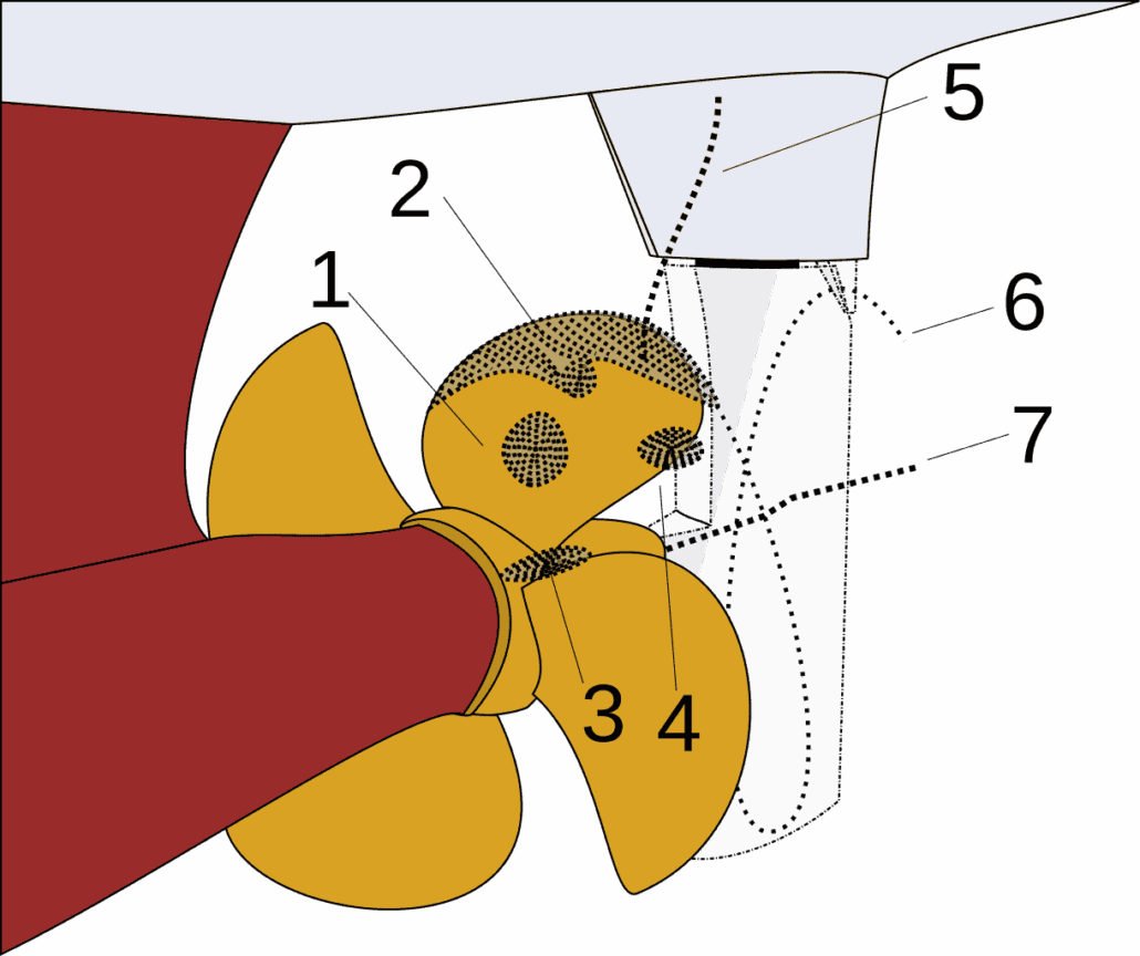
So cavitation is bad, and it arises from large pressure changes. But a propeller does not create a single uniform pressure field. The pressure varies due to many interacting parts of the propeller geometry. For this reason, we classify different types of cavitation based on the section of the propeller that generates the bubbles. (Figure 3‑1)
- Bubble cavitation
- Sheet cavitation
- Blade root cavitation
- Cloud cavitation
- Propeller hull cavitation
- Tip vortex cavitation
- Hub vortex cavitation
Region 1 signals a bad blade design. Bubble cavitation shows as some small region of damage in the middle of the propeller blade. This occurs due to uneven pressure distributions along the blade. Somehow, some section of the propeller created an excessive pressure loss, resulting in cavitation. This may occur due to interactions with the vessel hull. The hull creates an uneven flow of water that enters the propeller. Some radials sections along the propeller have faster inflow than others. With this uneven flow, one section of the propeller may generate greater suction than intended, resulting in bubble cavitation.
Region 2 shows sheet cavitation, which is fairly common, even in good blade designs. Sheet cavitation occurs across the entire outer face of the propeller blade. (Figure 3‑2) Small amounts of sheet cavitation, 5%-10% of the blade area, may be acceptable. Sheet cavitation signals that the propeller generates too large of a pressure drop. You are trying to fit too much thrust into too small of a blade area. There are two possible solutions: increase the propeller diameter, or increase the blade area.
Region 3 is another signal of a bad propeller design. Root cavitation arises from too much pressure drop near the root of the propeller blade. The easiest solution is to alter the blade section shape. Generate less pressure drop at the root of the blade. Shift that demand towards the middle of the blade radius.
Region 4 is similar to region 2. This cloud cavitation is a variation on sheet cavitation. It occurs when the cavitation begins near the trailing edges of the propeller. By the time the bubbles collapse, many already drifted off the blade. You deal with cloud cavitation the same as sheet cavitation (region 2).
Region 5 occurs due to bubbles generated by the propeller drifting onto the hull before collapsing. There are two solutions to propeller hull cavitation. First, eliminate the bubble generation on the propeller. The second solution is larger clearance between the propeller and the hull. As a good rule of thumb, the propeller clearance should be 10% of the propeller diameter. The larger clearance allows sufficient time for the bubbles to collapse before touching the hull. This includes any hull appendages such as the rudder.
Regions 6 and 7 are not a major structural concern. The tip vortex and hub vortex cavitation happen right on the edge of the propeller. So the bubbles never collapse against the propeller surface. But they do create a large amount of noise, which may become a concern for military applications.

3.0 Super-cavitation
If you can’t beat it, use it. For high speed vessels, sometimes cavitation is unavoidable. The propeller simply must pack a high thrust into a small area. These specialized cases call for super-cavitating propellers. (Figure 4‑1)
The super-cavitating propeller does not prevent cavitation; instead it guarantees cavitation in a predictable pattern. Remember that cavitation is only dangerous when the bubbles collapse. A super-cavitating propeller works carefully to ensure the bubbles never collapse until they leave the propeller blade. This drastically alters the performance of the propeller.
“When the cavity on the back of a propeller blade has spread until it covers the whole of the back, which is then no longer wetted, the propeller is said to be operating in the fully or super-cavitating regime. After the back of the section has become completely denuded of water, the increase in revolutions per minute cannot reduce pressure there any more, and so no additional lift can be generated by the back. On the face, however, pressure continues to increase with higher revolutions and so does the total thrust, although at a slower rate than before cavitation began.”
J.D. van Manen, P. van Oossanen [4]
These propellers show a distinctive wedge shape when viewed in cross section. (Figure 4‑2) That cross section shape means the pressure continues to drop as the bubbles travel across the blade face. If the pressure keeps dropping, the bubbles never collapse until they leave the propeller blade. The propeller remains safe from cavitation damage.


4.0 Conclusion
Treat cavitation like any other natural disaster. If you understand it, you can avoid it. Careful propeller design limits cavitation to only minor levels of sheet cavitation. Armed with this article, you now recognize the various signs of cavitation and what they mean. Forewarned is forearmed. Don’t let cavitation destroy your next propeller.
5.0 References
| [1] | BOH, “File: Cavitation,” Wikimedia Commons, 9 Oct. 2008. . Available: https://commons.wikimedia.org/wiki/File:Cavitation.svg. . |
| [2] | Liftarn, “File: Cavitation Propeller Damage,” Wikimedia Commons, 23 May 2007. . Available: https://commons.wikimedia.org/wiki/File:Cavitation_Propeller_Damage.JPG. . |
| [3] | TradeKorea.com, “Semi-Submersible Surface Propellers,” TradeKorea.com, . Available: https://www.tradekorea.com/product/detail/P362668/Semi-submersible-surface-propellers.html. . |
| [4] | P. v. O. J.D. van Manen, “Propulsion, Section 10: Other Propulsion Devices,” in Principles of Naval Architecture, 2nd Revision. Volume II, Resistance Propulsion and Vibration, USA, Society of Naval Architects and Marine Engineers, 1988, p. 242. |
| [5] | Tosaka, “Super cavitation Propeller,” Wikimedia Commons, 16 Sep. 2008. . Available: https://commons.wikimedia.org/wiki/File:Super_cavitation_Propeller_(-1)_NT.PNG. . |
| [6] | Wikipedia, “Axial Fan Design,” Wikimedia Commons, 12 October 2014. . Available: https://en.wikipedia.org/wiki/Axial_fan_design. . |
| [7] | D. S. N. J. E. B. Tony Burton, Wind Energy Handbook, New York: John Wiley & Sons, 2001. |
| [8] | The Hamburg Ship Model Basin, “Energy Saving Devices – Design and Optimization,” The Hamburg Ship Model Basin, 2017. . Available: https://www.hsva.de/our-services/numerical-predictions/cfd-esd-design-optimisation.html. . |
Share This Post
More Like This
 https://dmsonline.us/wp-content/uploads/2025/08/Clickbait.jpg
720
1280
Nicholas Barczak
/wp-content/uploads/2025/06/DMS-logo.svg
Nicholas Barczak2025-11-11 07:00:002026-02-02 09:08:54How to Buy a Towing Tank: Purchase and Design Guide
Marine Highways: Short Sea Shipping
Economics, Integration / Engineering, Miscellaneous, Support Services https://dmsonline.us/wp-content/uploads/2022/09/ClickBait_2.89.9-scaled-1.jpg
675
1200
Nate Riggins
/wp-content/uploads/2025/06/DMS-logo.svg
Nate Riggins2023-04-03 08:00:002025-08-15 10:36:17Electric Yacht Charging
 https://dmsonline.us/wp-content/uploads/2022/09/Lithium-Chemistries-Spider-Chart.webp
513
589
Nate Riggins
/wp-content/uploads/2025/06/DMS-logo.svg
Nate Riggins2023-03-06 08:00:002025-08-15 10:30:12Batteries for Electric Propulsion
 https://dmsonline.us/wp-content/uploads/2022/09/Slide21-Clickbait-scaled-1.jpg
675
1200
Nate Riggins
/wp-content/uploads/2025/06/DMS-logo.svg
Nate Riggins2023-01-30 08:00:002025-08-15 10:37:00Electric Yacht System Design
 https://dmsonline.us/wp-content/uploads/2022/09/M22006-ClickBait-scaled-1.jpg
675
1200
Nate Riggins
/wp-content/uploads/2025/06/DMS-logo.svg
Nate Riggins2022-12-05 08:00:002025-08-15 10:38:53Emergency Electric Propulsion
 https://dmsonline.us/wp-content/uploads/2022/04/ClickBait.jpg
720
1280
Nate Riggins
/wp-content/uploads/2025/06/DMS-logo.svg
Nate Riggins2022-04-04 07:00:002025-08-15 13:08:57Ever Given: Maneuvering Options
Ever Given: What We Don’t Know
Command and Surveillance, Fluid Dynamics, Miscellaneous, Ship Maneuvering, Ship Motion Control, Ship Response
Cranes on Ships: Introduction to Crane Integration
Auxiliary Systems, Mechanical Handling Systems, Miscellaneous, Replenishment SystemsAbout Us
Ship designs tailored to your mission. Engineering that advances profits.

